
ETABS Seismic Analysis of a Multi-Storey Building: A Practical Step-by-Step Guide
Introduction
ETABS seismic analysis is an important part of structural engineering, particularly when studying how multi-storey buildings respond to earthquake-induced forces. ETABS is a structural analysis and design software used to model building structures, define loading conditions, perform dynamic analysis and evaluate structural behaviour.
Civil engineers and structural designers use ETABS to study beams, columns, slabs, structural walls, building deformations, storey drift, base shear and other important structural response parameters.
Understanding seismic analysis is useful for Civil Engineering students, diploma holders, structural engineering graduates and working professionals who want to develop practical structural modelling and analysis skills.
If you are searching for ETABS training in Yelahanka, structural analysis courses in Bangalore or Civil CADD training near me, this guide explains how a typical multi-storey building analysis project can be developed using ETABS.
This practical tutorial uses an illustrative reinforced concrete building model to explain the workflow from structural modelling to earthquake load application, response spectrum analysis and result interpretation.
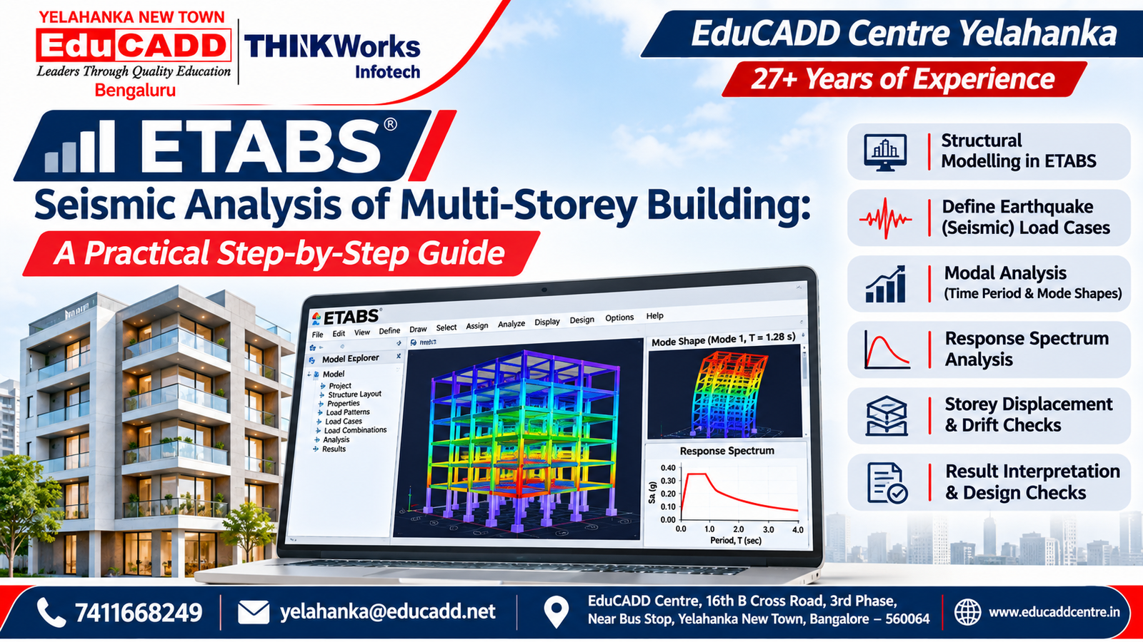
1. What Is ETABS Seismic Analysis?
ETABS seismic analysis is the process of evaluating how a building structure responds to earthquake-related ground motion using a structural analysis model.
During an earthquake, ground movement produces inertia forces in a building. These forces depend on several factors, including:
- Building mass
- Structural stiffness
- Natural periods
- Damping characteristics
- Structural configuration
- Ground motion characteristics
- Soil and site conditions
- Applicable seismic design requirements
ETABS allows engineers to develop a structural model and study its behaviour under specified loading conditions.
The software can be used to examine:
- Natural frequencies and mode shapes
- Modal mass participation
- Seismic response
- Base shear
- Storey displacement
- Inter-storey drift
- Torsional response
- Member forces
- Support reactions
- Structural design results
Seismic analysis is not simply about applying an earthquake load and clicking Run Analysis. The quality of the results depends on correct modelling assumptions, engineering judgement, code requirements and validation.
2. Why Is Seismic Analysis Important in Building Design?
Buildings experience different types of loads during their service life.
These include:
Dead Loads
Dead loads are permanent loads arising from structural components and other permanently attached elements.
Examples include:
- Beams
- Columns
- Slabs
- Structural walls
- Permanent finishes
- Fixed building components
Live Loads
Live loads are variable imposed loads associated with the use and occupancy of a building.
Examples include:
- Occupants
- Movable furniture
- Storage loads
- Other occupancy-related loads
Wind Loads
Wind loads act on the building because of wind pressure and suction.
Their effects depend on building height, shape, location, exposure and applicable design requirements.
Earthquake Loads
Earthquake effects arise from ground acceleration and the resulting inertia forces in the structure.
The structural response depends on the building’s mass, stiffness, dynamic characteristics and the characteristics of the ground motion.
A structural engineer must consider the relevant loading conditions and combinations required by the governing design standards.
3. Important Concepts to Understand Before Starting ETABS Seismic Analysis
Before creating the structural model, understand the following engineering concepts.
1. Seismic Zone and Seismic Hazard
Seismic hazard information helps determine the earthquake-related design requirements applicable to a building location.
The relevant hazard parameters must be obtained from the applicable design standard and project information.
Do not select seismic parameters based only on a generic online table.
2. Natural Time Period
The natural time period represents the time taken by a structure to complete one cycle of free vibration in a particular mode.
It is influenced by structural mass and stiffness.
Buildings with different heights, structural systems and stiffness characteristics can have different natural periods.
3. Mode Shapes
A mode shape represents a characteristic deformation pattern associated with a natural vibration mode.
The first few modes help engineers understand how a building may move dynamically.
Typical responses include:
- Translational movement in the X direction
- Translational movement in the Y direction
- Torsional movement around the vertical axis
4. Modal Mass Participation
Modal mass participation indicates how much of the building’s mass participates in a particular vibration mode or group of modes.
Engineers review cumulative modal participation to determine whether sufficient modes have been considered under the governing analysis requirements.
5. Response Spectrum
A response spectrum represents the maximum response of a family of idealized single-degree-of-freedom systems as a function of their natural period or frequency for a specified ground-motion and damping basis.
A response spectrum function is used as an input for response-spectrum analysis.
6. Base Shear
Base shear represents the total horizontal seismic force transferred to the base of the structure for the relevant analysis case or combination.
7. Storey Displacement
Storey displacement describes the lateral movement of a building floor relative to its reference position.
8. Storey Drift
Inter-storey drift is the relative lateral displacement between two consecutive floors.
It is an important parameter for assessing building deformation under lateral loading.
9. Torsional Response
Torsional response occurs when a building experiences twisting due to the distribution of mass, stiffness and lateral forces.
Irregular geometry and eccentricity can influence this response.
10. P-Delta Effect
P-Delta effects are second-order effects associated with axial forces acting through lateral displacements.
They may become important when evaluating the stability and behaviour of structures under significant deformation.
4. Practical Project: Multi-Storey Building Seismic Analysis Using ETABS
Let’s consider an illustrative eight-storey reinforced concrete residential building for a training project.
The purpose is to understand the software workflow, not to provide a construction-ready structural design.
Project objectives
The training project will cover:
- Building geometry
- Structural grids
- Storey levels
- Material properties
- Beam and column sections
- Slab modelling
- Structural walls, where applicable
- Gravity loads
- Mass source
- Modal analysis
- Response spectrum analysis
- Seismic response evaluation
- Structural design workflow
- Engineering report preparation
Project information to establish
Before modelling, prepare a design basis document containing:
| Project parameter | Information required |
|---|---|
| Building type | Residential or commercial |
| Number of storeys | Illustrative eight-storey model |
| Structural system | Selected reinforced concrete system |
| Building location | Actual project location |
| Soil information | Based on project geotechnical data |
| Material grades | Specified concrete and reinforcement grades |
| Floor levels | Architectural and structural drawings |
| Loading | Applicable dead and imposed loads |
| Seismic parameters | From governing design standard |
| Design combinations | Applicable code requirements |
The actual dimensions, member sizes, materials and design parameters must be established by the responsible structural engineer.
5. Step-by-Step ETABS Structural Modelling Workflow
Step 1: Create a New ETABS Model
Open ETABS and create a new structural model.
Set the appropriate units for the project.
Select the required grid system and storey configuration.
For the illustrative eight-storey project, define the building grids and floor elevations based on the training drawings.
Step 2: Define Grid Lines and Storey Levels
Create the horizontal grid system.
Define:
- Grid spacing in the X direction
- Grid spacing in the Y direction
- Number of grid lines
- Ground floor level
- Intermediate floor levels
- Roof level
Correct grid and storey definitions help maintain consistency during structural modelling.
Step 3: Define Material Properties
Open the material properties section.
Define the materials required for the building.
Typical materials include:
- Concrete
- Reinforcing steel
- Structural steel, if applicable
Enter the relevant properties using approved project specifications and the applicable design requirements.
Important material properties may include:
- Unit weight
- Modulus of elasticity
- Poisson’s ratio
- Concrete strength
- Reinforcement yield strength
- Other required design parameters
Incorrect material properties can significantly affect the analysis results.
Step 4: Define Beam and Column Sections
Create the required structural member sections.
For example:
- Rectangular beams
- Rectangular columns
- Other specified structural sections
Define their dimensions and assign the appropriate materials.
Do not choose member sizes arbitrarily for an actual building. Preliminary sizes must be checked and revised through an appropriate structural design process.
Step 5: Model Columns and Beams
Use the grid system and storey levels to model the structural frame.
Create columns between the appropriate levels.
Connect beams between structural supports.
Check:
- Member connectivity
- Beam-column intersections
- Member orientation
- Structural continuity
- Frame alignment
A disconnected or incorrectly connected structural element can produce unreliable results.
Step 6: Model Slabs and Structural Walls
Create floor slab elements using suitable area or shell modelling approaches.
Where the structural system includes shear walls or other structural walls, model them according to the intended structural behaviour.
Consider:
- Slab thickness
- Wall thickness
- Element connectivity
- Mesh requirements
- Openings
- Boundary conditions
The element formulation and mesh should be suitable for the intended analysis.
Step 7: Assign Supports and Boundary Conditions
Define support conditions at the structural base.
The support model should reflect the intended foundation and soil-structure assumptions.
A fixed-base assumption should not be used automatically for every project.
Check the foundation design basis and the effect of any support assumptions on the structural response.
Step 8: Assign Diaphragms
Floor diaphragms help represent how floor systems distribute lateral loads to vertical structural elements.
Depending on the floor system and structural configuration, engineers may use appropriate rigid or semi-rigid diaphragm modelling assumptions.
Check that diaphragm assignments are consistent with the structural system.
6. Define Load Patterns, Load Cases and Mass Source
Once the structural model is ready, define the loading information.
A. Dead Load
Define the dead load pattern.
Include relevant structural self-weight and other applicable permanent loads.
Check the self-weight multiplier to avoid counting the structural self-weight twice.
B. Live Load
Define the imposed loading appropriate to the building occupancy and applicable standards.
C. Wall and Floor Finish Loads
Include appropriate loads from:
- Masonry walls
- Floor finishes
- Ceiling systems
- Permanent services
- Other applicable components
D. Other Applicable Loads
Depending on the project, consider:
- Wind loads
- Equipment loads
- Water tank loads
- Other relevant imposed actions
E. Define the Mass Source
The mass source is especially important for dynamic analysis.
It determines how the building’s mass is represented for modal and seismic calculations.
Define it using the appropriate self-weight, permanent load and applicable imposed-load contributions required by the governing standard.
Check that the mass source does not unintentionally omit or duplicate loads.
F. Understand Load Patterns and Load Cases
A load pattern identifies the type of load and how it is assigned to the structure.
A load case specifies how the load is applied and how the structural response is calculated.
This distinction is important when preparing seismic analysis.
Refer to the official ETABS Load Cases documentation.
7. How to Perform Modal Analysis in ETABS
Modal analysis helps determine the dynamic characteristics of the building.
It is an essential step before carrying out a response-spectrum analysis based on modal superposition.
Step 1: Define a Modal Load Case
Open the modal case settings.
Choose the appropriate analysis approach.
Common methods include:
- Eigenvector analysis
- Ritz vector analysis
The choice depends on the analysis objective and loading requirements.
Step 2: Define the Number of Modes
Select a suitable number of modes for the building model.
The number should be sufficient to capture the required dynamic participation under the governing design requirements.
Do not select an arbitrary number without checking the cumulative mass participation and relevant analysis criteria.
Step 3: Run Modal Analysis
Run the modal analysis.
Review:
- Natural periods
- Natural frequencies
- Mode shapes
- Translational modes
- Torsional modes
- Modal mass participation
Step 4: Interpret the Mode Shapes
Examine the mode shapes to understand the building’s dynamic behaviour.
For example:
- A translational mode may show lateral movement primarily along one horizontal direction.
- Another mode may show movement along the perpendicular direction.
- A torsional mode may show twisting behaviour.
Unexpected mode shapes may indicate modelling issues, irregularities or incorrect structural assumptions that require investigation.
Read the official ETABS Modal Case Data documentation.
8. How to Define Response Spectrum Analysis in ETABS
Response-spectrum analysis is a commonly used dynamic analysis method for evaluating building response to earthquake excitation.
The response spectrum function must be developed from the applicable design requirements and appropriate project parameters.
Step 1: Prepare the Design Response Spectrum
Determine the required spectrum information using the governing seismic design standard.
Consider:
- Applicable seismic hazard parameters
- Soil or site classification
- Building importance category
- Structural system
- Damping assumptions
- Relevant period range
- Other code-specific parameters
Do not use an arbitrary response-spectrum curve downloaded from the internet.
Step 2: Define the Response Spectrum Function
Open the response-spectrum function settings in ETABS.
Enter the required period and spectral acceleration data or use an appropriate supported function definition.
Check the units carefully.
Step 3: Create a Response Spectrum Load Case
Open the load cases menu.
Create a new response-spectrum load case.
Select the previously defined modal case as the basis for modal superposition.
Define the acceleration directions and relevant scale factors.
The scale factor must be dimensionally consistent with the selected ETABS unit system.
Step 4: Select Modal Combination Method
Common modal combination methods include:
- CQC – Complete Quadratic Combination
- SRSS – Square Root of Sum of Squares
The appropriate method depends on the applicable design standard and analysis requirements.
CQC accounts for modal cross-correlation and damping effects in its formulation, while SRSS uses a simpler statistical combination.
Do not select a method merely because it is the software default.
Step 5: Define Directional Combination
Specify the appropriate method for combining horizontal and other required acceleration directions.
Check the governing code requirements for directional effects and accidental eccentricity.
Step 6: Run Response Spectrum Analysis
Run the analysis and examine the output.
Review the relevant structural response results and verify that the input parameters are consistent with the design basis.
For detailed settings, consult the official ETABS Response Spectrum Load Case documentation.
9. How to Review Seismic Analysis Results in ETABS
After completing the analysis, engineers must interpret the results rather than simply accepting the software output.
1. Base Shear
Review the total base shear obtained from the relevant seismic analysis cases.
Where required, compare dynamic analysis results with the corresponding code-based reference force and apply any required scaling procedure.
2. Storey Displacement
Review the displacement at different floor levels.
Plot the displacement profile to understand how the building responds across its height.
3. Inter-Storey Drift
Examine relative lateral displacement between consecutive floors.
Check the calculated drift against the limits specified by the governing standard.
4. Torsional Behaviour
Review the rotation and displacement of floor diaphragms.
Investigate unexpected torsional response and irregularities.
5. Storey Shear
Review the distribution of lateral forces and storey shear along the building height.
6. Storey Stiffness
Compare storey stiffness to identify potentially weak or soft-storey behaviour.
7. Member Forces
Review the structural forces in:
- Beams
- Columns
- Structural walls
- Other relevant structural components
8. Support Reactions
Review the support reactions and their consistency with the applied loading and overall equilibrium.
9. Deformed Shape
Examine the deformed shape under different loading cases.
Look for unexpected movement, instability or modelling errors.
10. Structural Design Checks
Review applicable design results and identify members requiring further engineering assessment or redesign.
Software-generated results must always be checked against the governing design requirements.
10. How to Identify Common Structural Modelling and Analysis Errors
The quality of an ETABS analysis depends on the quality of the structural model.
Some common issues include:
1. Incorrect Geometry
Incorrect grid spacing or floor elevations can change the structural representation.
2. Incorrect Member Connectivity
Disconnected beams, columns or structural walls can affect load transfer.
3. Incorrect Material Properties
Incorrect material grades or stiffness properties can change the structural response.
4. Incorrect Mass Source
An incorrect mass source can lead to inappropriate dynamic characteristics and seismic response.
5. Incorrect Load Assignments
Missing or duplicated loads may produce misleading results.
6. Incorrect Diaphragm Assignments
Unrealistic diaphragm assumptions may affect lateral force distribution.
7. Insufficient Modal Coverage
An inadequate modal basis may fail to capture the required dynamic response.
8. Incorrect Response Spectrum Input
Incorrect spectrum values, damping assumptions or units can produce unreliable analysis results.
9. Ignoring Torsional Effects
Torsional behaviour should be reviewed according to the building’s configuration and design requirements.
10. Ignoring P-Delta Effects
Where required, second-order effects must be considered using an appropriate analysis procedure.
11. Ignoring Analysis Warnings
Review warnings, instability messages and unusual output before accepting the model.
12. Accepting Software Design Results Without Engineering Review
ETABS is a calculation and modelling tool. It does not replace engineering judgement, independent checks or the responsible engineer’s approval.
11. Practical ETABS Projects for Civil Engineering Students
Students can improve their understanding by working on complete structural analysis projects.
Project 1: Multi-Storey Residential Building
Develop:
- Building grids
- Storey levels
- Beam and column models
- Slab modelling
- Gravity load cases
- Modal analysis
- Response spectrum analysis
- Structural result review
Project 2: Commercial Building Structural Analysis
Study:
- Structural framing
- Floor loading
- Lateral load behaviour
- Dynamic characteristics
- Storey drift
- Member design results
Project 3: Building with Shear Walls
Develop a model containing suitable structural walls.
Compare the structural behaviour of alternative model configurations under consistent assumptions.
Project 4: Structural Irregularity Study
Prepare illustrative models to understand the influence of:
- Plan irregularity
- Vertical irregularity
- Stiffness variation
- Mass distribution
- Torsional response
Project 5: Comparative Modal Analysis
Compare the modal behaviour of selected structural configurations.
Review the effect of different modelling assumptions on natural periods and mode shapes.
Recommended Project Deliverables
For a complete student portfolio, prepare:
- Structural design basis.
- ETABS model file.
- Building geometry.
- Material and section definitions.
- Load patterns and combinations.
- Mass source information.
- Modal analysis results.
- Response spectrum analysis results.
- Storey displacement and drift tables.
- Base shear calculations and comparisons.
- Structural design review.
- Project documentation and presentation.
Use clearly identified illustrative assumptions for training projects. Do not present an educational model as an approved construction design.
12. Important Indian Standards and Seismic Design Considerations
Structural engineers must follow the applicable Indian Standards, amendments, project specifications and local authority requirements.
Relevant standards may include:
- IS 1893 – Earthquake-resistant design criteria
- IS 456 – Plain and reinforced concrete
- IS 13920 – Ductile detailing of reinforced concrete structures
- IS 875 – Design loads for buildings and structures
Important standards update: BIS issued a notification in November 2025 concerning revised IS 1893 editions, but that earlier notification was withdrawn with immediate effect through a subsequent notification dated 3 March 2026. Therefore, do not rely on the withdrawn transition dates. Check the current applicable editions, amendments and project requirements through the official BIS Know Your Standard portal before preparing seismic design inputs.
The applicable standard must be confirmed for the specific project and its approval authority.
The objective of this article is to explain the software workflow, not to prescribe seismic design values or replace a qualified structural engineer’s design.
13. Career Opportunities After ETABS Training
Learning ETABS can help Civil Engineering students and graduates develop skills relevant to structural analysis and building design.
Possible career paths include:
1. Structural Design Assistant
Supports structural modelling, calculations, design documentation and drawing coordination.
2. Junior Structural Engineer
Assists with structural analysis, design checks and project documentation under appropriate engineering supervision.
3. Structural Analysis Engineer
Works with structural modelling, load cases, analysis results and structural response evaluation.
4. Civil Structural Design Engineer
Works on building structural systems, member design, analysis and documentation, subject to the required academic qualifications and experience.
5. Structural BIM Modeller
Develops structural models and coordinates structural information with other building disciplines.
6. ETABS Modeller
Supports the preparation and maintenance of building models for structural analysis.
7. Structural Engineering Project Assistant
Assists engineering teams with calculations, technical documentation and project coordination.
Skills to Develop Alongside ETABS
- Engineering Mechanics
- Structural Analysis
- Reinforced Concrete Design
- Steel Structure Fundamentals
- Earthquake Engineering
- Engineering Drawing
- Load Calculations
- Indian Structural Design Standards
- Technical Report Preparation
- Excel and Engineering Calculations
ETABS knowledge alone does not guarantee employment. A strong understanding of structural engineering fundamentals, design standards, technical calculations and project work is essential.
14. ETABS Training in Yelahanka, Bangalore at EduCADD Centre
Are you searching for:
- ETABS course in Yelahanka?
- ETABS training in Bangalore?
- Structural analysis course near me?
- ETABS classes in Yelahanka New Town?
- Structural design software training in Bangalore?
- Civil Engineering software courses near me?
- ETABS seismic analysis training?
- ETABS course for Civil Engineering students?
- Structural modelling course in North Bangalore?
- ETABS course with placement assistance?
- STAAD.Pro and ETABS training in Bangalore?
EduCADD Centre Yelahanka offers ETABS training for Civil Engineering students, diploma holders, structural engineering students, graduates and working professionals.
With 27+ years of experience, EduCADD Centre focuses on practical software education, structural modelling, analysis workflows, design concepts and project-based learning.
ETABS Course Training Coverage
Module 1: ETABS Fundamentals
- Software interface
- Project setup
- Units and settings
- Building grids
- Storey levels
Module 2: Structural Modelling
- Beam modelling
- Column modelling
- Slab modelling
- Structural walls
- Material properties
- Section properties
Module 3: Loading
- Dead loads
- Live loads
- Load patterns
- Load assignments
- Load cases
- Load combinations
Module 4: Structural Analysis
- Analysis setup
- Structural response
- Deformed shapes
- Support reactions
- Member forces
- Result interpretation
Module 5: Building Design
- Concrete member design concepts
- Beam design
- Column design
- Slab design concepts
- Structural wall design concepts
- Design checks
Module 6: Seismic Analysis
- Earthquake loading concepts
- Modal analysis
- Response spectrum analysis
- Building behaviour
- Seismic response interpretation
- Structural result review
Module 7: Project Documentation
- Analysis tables
- Design reports
- Model verification
- Project presentation
Module 8: Practical Structural Project
- Multi-storey building modelling
- Load assignments
- Structural analysis
- Result interpretation
- Design workflow
- Project documentation
Explore the ETABS Course Training in Yelahanka, Bangalore for the published course modules and training information.
You can also explore Civil CADD Courses at EduCADD Centre Yelahanka for Revit Structure, STAAD.Pro, AutoCAD Civil and other civil engineering software options.
Visit All CADD Courses at EduCADD Centre to explore additional engineering software training.
Students can contact the centre to confirm current course availability, batch timings, fees, duration, syllabus and practical project coverage.
EduCADD Centre provides practical project guidance, portfolio development, resume preparation, interview preparation, career guidance and placement assistance for eligible students. Placement assistance does not guarantee a job or employment.
Conclusion
ETABS seismic analysis is an important skill for students and professionals interested in structural engineering and multi-storey building design.
By understanding structural modelling, material properties, load assignments, mass source, modal analysis, response spectrum analysis and structural result interpretation, learners can develop a better understanding of how buildings respond to earthquake forces.
Practical projects involving residential buildings, commercial structures and shear wall systems help students connect structural engineering theory with software-based analysis.
If you want to develop practical ETABS modelling and structural analysis skills, explore ETABS training at EduCADD Centre Yelahanka, Bangalore.
Learn. Model. Analyse. Design. Build your structural engineering skills with EduCADD Centre Yelahanka.
Contact EduCADD Centre Yelahanka
EduCADD Centre Yelahanka
27+ Years of Experience
Phone: 7411668249
Email: yelahanka@educadd.net
Address: EduCADD Centre, 16th B Cross Road, 3rd Phase, Near Bus Stop, Yelahanka New Town, Bangalore – 560064
Website: https://www.educaddcentre.in
EduCADD Centre – Leaders Through Quality Education.