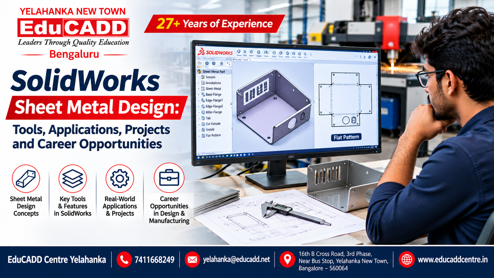
SolidWorks Sheet Metal Design: Tools, Applications, Projects and Career Opportunities
SolidWorks Sheet Metal Design: Tools, Applications, Projects and Career Opportunities
Introduction
Sheet metal design is an important part of modern mechanical engineering and manufacturing. It involves designing components using thin metal sheets that are cut, bent, punched, folded and formed into functional products.
From automotive components and electrical enclosures to industrial machinery and HVAC systems, sheet metal parts are used across several industries.
Today, mechanical design engineers use CAD software to develop accurate 3D sheet metal models, prepare engineering drawings and generate flat patterns for manufacturing.
SolidWorks Sheet Metal Design provides specialized tools that help engineers develop sheet metal components and visualize how they will look before manufacturing.
If you are searching for SolidWorks training in Yelahanka, mechanical CAD courses in Bangalore or sheet metal design training near me, this guide will help you understand the software, important tools, practical applications and career opportunities.
What Is SolidWorks Sheet Metal Design?
SolidWorks Sheet Metal is a specialized design environment used to create sheet metal components with defined thickness, bends, flanges and other manufacturing features.
Unlike conventional solid modelling, sheet metal modelling includes tools and parameters that help designers develop folded components and generate their corresponding flat patterns.
The software is useful for:
- Designing sheet metal enclosures
- Creating electrical panel boxes
- Developing mounting brackets
- Designing machine covers
- Preparing sheet metal ducts
- Creating folded metal components
- Generating manufacturing drawings
- Preparing flat patterns for fabrication
Understanding sheet metal design can help mechanical engineering students connect CAD modelling with real manufacturing processes.
Important SolidWorks Sheet Metal Tools
1. Base Flange / Tab
Base Flange is commonly used to create the initial sheet metal body using a sketch and specified material thickness.
It provides the foundation for developing other sheet metal features.
2. Edge Flange
Edge Flange creates additional flanges along selected edges of a sheet metal component.
It is commonly used when designing brackets, trays, boxes and enclosures.
3. Miter Flange
Miter Flange helps create connected flange sections along selected edges.
It is useful when developing more complex folded sheet metal shapes.
4. Hem
The Hem feature creates a folded edge in a sheet metal component.
It can be used to improve edge finishing, reduce exposed sharp edges and provide additional stiffness depending on the design.
5. Jog
Jog creates an offset in a sheet metal component using two bends.
It is useful for developing components that require different surface levels.
6. Closed Corner
Closed Corner helps close gaps between adjoining sheet metal flanges.
This feature is useful when designing enclosures and folded components.
7. Flat Pattern
Flat Pattern converts a folded sheet metal model into its unfolded representation.
It is particularly important for preparing manufacturing documentation and understanding the developed sheet shape before bending.
Understanding Bend Allowance and K-Factor
Bend allowance and K-factor are important concepts in sheet metal design.
When a metal sheet is bent, the material on the outer side stretches while the material on the inner side compresses.
Designers must account for this deformation when calculating the developed flat length.
Bend Allowance: The length of material along the bend region used in flat-pattern calculations.
Bend Deduction: The value subtracted from the outside dimensions to determine the developed flat length.
K-Factor: A ratio used to locate the neutral axis relative to the material thickness.
The correct values depend on material properties, thickness, bend radius and manufacturing processes.
Understanding these concepts helps designers create more accurate flat patterns.
Industries That Use Sheet Metal Design
Automotive Industry
Sheet metal design is used in vehicle body panels, brackets, housings and various fabricated components.
Electrical Industry
Electrical control panels, distribution board enclosures and equipment cabinets often use sheet metal components.
HVAC Industry
Ventilation ducts, air handling components and sheet metal fittings are important applications.
Industrial Machinery
Machine covers, protective guards, mounting brackets and equipment enclosures are commonly developed using sheet metal design.
Consumer Products
Metal cabinets, appliance enclosures and equipment housings also use sheet metal fabrication.
Practical SolidWorks Sheet Metal Projects for Students
Practical projects help students understand how software features are applied to real engineering components.
Here are five useful projects to include in your mechanical design portfolio.
Project 1: Sheet Metal L-Bracket
Practise Base Flange, Edge Flange, holes, bends and flat pattern generation.
Project 2: Electrical Enclosure
Create a box-shaped enclosure with flanges, cut-outs, mounting holes and suitable dimensions.
Project 3: Equipment Housing
Develop a sheet metal housing using bends, closed corners and other sheet metal features.
Project 4: U-Channel Component
Practise flange creation, bend parameters and engineering drawing preparation.
Project 5: Mounting Bracket
Develop a folded 3D model and its corresponding flat pattern for fabrication.
For each project, try to prepare:
- 3D component model
- Material and thickness information
- Bend parameters
- Flat pattern
- Engineering drawing
- Dimensions and annotations
- Manufacturing considerations
These projects can help demonstrate your practical mechanical design knowledge during interviews.
What Skills Should You Learn Alongside SolidWorks?
To strengthen your mechanical design knowledge, consider developing the following skills:
- Engineering drawing interpretation
- GD&T fundamentals
- 3D part modelling
- Assembly modelling
- Sheet metal design
- Surface modelling
- Manufacturing processes
- Material selection
- Technical documentation
- Basic quality inspection concepts
You can also explore CATIA, Creo and Siemens NX according to your preferred mechanical engineering specialization.
Career Opportunities After Learning SolidWorks Sheet Metal Design
SolidWorks and sheet metal design knowledge can be useful in several mechanical engineering roles.
Mechanical Design Engineer
Works on designing mechanical components, assemblies and engineering documentation.
Sheet Metal Design Engineer
Develops sheet metal components, enclosures, brackets and fabrication drawings.
CAD Design Engineer
Creates 2D drawings, 3D models and technical documentation.
Product Design Engineer
Works on product development, component design and design improvement.
Manufacturing Design Engineer
Works with product design and manufacturing requirements to develop production-ready components.
Career opportunities depend on technical skills, practical project experience, qualifications and employer requirements.
Why Should Mechanical Engineering Students Learn SolidWorks?
Mechanical engineering students need more than theoretical knowledge to prepare for design and manufacturing careers.
Learning SolidWorks can help students develop skills in:
- 3D component modelling
- Mechanical assemblies
- Sheet metal modelling
- Engineering drawings
- Design modifications
- Manufacturing documentation
- Practical project development
Working on real-world-style projects can also help students understand how mechanical components are designed and prepared for production.
SolidWorks Training in Yelahanka, Bangalore
Are you searching for:
- SolidWorks training in Yelahanka?
- SolidWorks courses in Bangalore?
- Mechanical CAD training near me?
- Sheet metal design training?
- Mechanical design courses in North Bangalore?
- CAD CAM training in Yelahanka New Town?
- Mechanical engineering software courses in Bangalore?
- SolidWorks classes near Yelahanka?
EduCADD Centre Yelahanka provides mechanical CAD software training options for engineering students, diploma holders, graduates and working professionals.
Mechanical training areas include:
- SolidWorks
- CATIA
- Creo
- AutoCAD Mechanical
- Siemens NX CAD
- ANSYS
- Mastercam
- SolidCAM
- Fusion 360
With 27+ years of experience in professional education, EduCADD Centre focuses on practical software learning, engineering projects and career-oriented skill development.
Students can contact the centre to enquire about current course coverage, practical assignments, batch schedules and fees.
Why Choose EduCADD Centre Yelahanka?
EduCADD Centre Yelahanka provides software training across multiple technical disciplines.
Students can explore:
- Mechanical CADD
- Civil CADD
- Electrical CADD
- BIM
- Interior Design
- Project Planning and Management
- IT and Software Courses
Training support includes practical software sessions, project guidance, resume preparation, interview preparation and placement assistance.
The appropriate course should be selected according to your educational background and career objectives. Placement assistance does not guarantee employment.
Conclusion
SolidWorks Sheet Metal Design is a valuable technical skill for mechanical engineering students interested in product design, fabrication and manufacturing.
Learning Base Flange, Edge Flange, Hem, Jog, Closed Corner and Flat Pattern tools can help students understand how sheet metal components are developed from initial sketches to manufacturing documentation.
Combine these software skills with engineering drawing knowledge, GD&T, material understanding and practical projects to develop a stronger mechanical design portfolio.
If you want to learn SolidWorks and other mechanical CAD software, contact EduCADD Centre Yelahanka for course details and upcoming batches.
Contact EduCADD Centre Yelahanka
Start developing your mechanical design skills with EduCADD Centre Yelahanka, Bangalore.
Contact EduCADD Centre Yelahanka for course details, fees, upcoming batches and career guidance.
📞 7411668249
📧 yelahanka@educadd.net
📍 EduCADD Centre, 16th B Cross Road, 3rd Phase, Near Bus Stop, Yelahanka New Town, Bangalore – 560064
🌐 www.educaddcentre.in
FAQs about Solidworks Training at EduCADD Centre Yelahanka Bangalore
Learn Mechanical CAD Software at EduCADD Centre Yelahanka Bangalore
Looking to develop your mechanical design skills?
Join EduCADD Centre Yelahanka to explore practical training in SolidWorks, CATIA, Creo, AutoCAD Mechanical and other engineering design software.
Contact us for course details and upcoming batches.
📞 7411668249
📍 EduCADD Centre, 16th B Cross Road, 3rd Phase, Near Bus Stop, Yelahanka New Town, Bangalore – 560064